YOUR CART
- No products in the cart.
Subtotal:
$0.00
Click here to see detailed information about the product
| Manufacturer | Tides Marine |
|---|---|
| Product Code | RUDDER BEARINGS |
| Product Line | PORT |
Price $560.97
Description
RPBH-D-2250-00 – Tides Marine Rudder Port Bearing Type D for a 2 1/4 inch rudder stock.
Replacement Bearing and Seal.
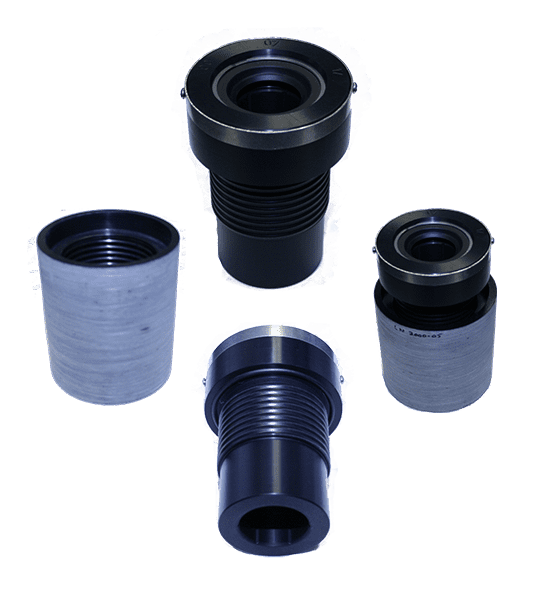
The Tides Marine Type-D rudder port is an integrated approach to rudder port installation. It is for boats constructed of FRP. It can be used for new boat construction and is also easy to use as a retrofit for replacing other types of conventional rudder ports. No tooling is required.
The Type-D is a sealed bearing consisting of a UHMW housing with a nitrile rubber lip seal. It eliminates metal-to-metal abrasion and electrolytic corrosion.
The Type-D kit includes the bearing housing, which has a threaded OD, and a matching epoxy FRP “liner”.
The liner can be laminated into an opening in the hull. Once the liner is laminated into the boat structure, it provides a preformed cavity matching the bearing profile. The bearing can then be threaded in and out for easy removal or replacement.

The Tides Marine Type D system components include a FRP liner and the Type D bearing and seal.
Molded from FRP and compatible with polyester, vinylester and epoxy systems, each Type D liner has an internal thread to accept its corresponding rudder bearing and seal.
The Type D rudder bearing and seal assembly consists of a one-piece UHMW housing with a nitrile lip seal. The UHMW bearing eliminates metal-to-metal contact and associated problems of abrasion and electrolytic corrosion. They are 100% watertight. Their performance characteristics match those of other Tides Marine rudder ports in that they are quiet, smooth and vibration free.
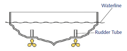
Type 1: Molds with an existing “flat” at the rudder port location. This installation will use the standard flange-type liner.
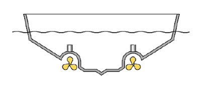
Type 2: Molds which require modification to achieve a “flat” surface or pocket for mounting a standard flange-type liner.

Type 3: Molds which require modification to accept an angled liner to match dead rise and rocker angles.
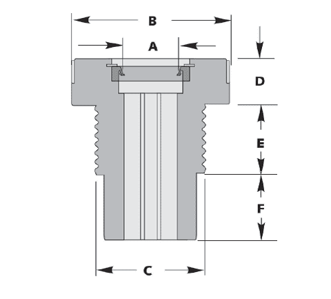 |
To determine which Type D to order, all you need is the exact diameter of your rudder stock (.000”). Assembly specifications are detailed in the Imperial and Metric Size pages. Confirm clearances and determine what, if any, mold modifications will be necessary. If necessary, please contact Tides Marine to discuss your installation parameters before placing your order. |

| Rudder |
Flange |
Thread |
Flange |
Thread |
Base |
Retaining |
Part Number |
Part Number |
|---|---|---|---|---|---|---|---|---|
| 1 | 3 | 2 1/2 | 1 1/2 | 2 11/16 | 1 9/16 | 185 | RPB-D-1000-00 | RPBH-D-1000-00 |
| 1 1/4 | 2 | 2 1/2 | 1 1/2 | 2 11/16 | 1 9/16 | 206 | RPB-D-1250-00 | RPBH-D-1250-00 |
| 1 3/8 | 3 | 2 1/2 | 1 1/2 | 2 11/16 | 1 9/16 | 212 | RPB-C-1375-00 | RPBH-C-1375-00 |
| 1 1/2 | 4 | 3 1/4 | 1 1/2 | 2 15/32 | 1 13/16 | 250 | RPB-C-1500-00 | RPBH-C-1500-00 |
| 1 3/4 | 4 | 3 1/4 | 1 1/2 | 2 15/32 | 1 13/16 | 250 | RPB-D-1750-00 | RPBH-D-1750-00 |
| 2 | 4 1/2 | 3 1/2 | 1 3/4 | 2 15/32 | 2 1/16 | 300 | RPB-C-2000-00 | RPBH-C-2000-00 |
| 2 1/4 | 4 1/2 | 3 1/2 | 1 3/4 | 2 15/32 | 2 1/16 | 325 | RPB-D-2250-00 | RPBH-D-2250-00 |
| 2 1/2 | 5 | 4 1/4 | 1 3/4 | 2 15/32 | 2 9/16 | 350 | RPB-D-2500-00 | RPBH-D-2500-00 |
| 2 3/4 | 5 | 4 1/4 | 1 3/4 | 2 15/32 | 2 9/16 | 375 | RPB-D-2750-00 | RPBH-D-2750-00 |
| 3 | 6 | 5 1/4 | 1 1/2 | 2 15/16 | 2 13/16 | 400 | RPB-D-3000-00 | RPBH-D-3000-00 |
| 3 1/2 | 6 | 5 1/4 | 1 1/2 | 2 15/16 | 2 13/16 | 450 | RPB-D-3500-00 | RPBH-D-3500-00 |
| 4 | 6 1/2 | 5 1/2 | 1 1/2 | 2 15/16 | 3 13/16 | 500 | RPB-D-4000-00 | RPBH-D-4000-00 |
| 4 1/4 | 6 1/2 | 5 1/2 | 1 1/2 | 2 15/16 | 3 13/16 | 525 | RPB-D-4000-00 | RPBH-D-4000-00 |
| 4 1/2 | 6 1/2 | 5 1/4 | 1 1/2 | 2 15/16 | 3 13/16 | 550 | RPB-D-4500-00 | RPBH-D-4500-00 |
Tide Marine offers many custom sizes and dimensions. Please call for any size or dimension you do not see here.
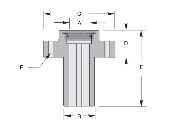
| Rudder |
Flange |
Thread |
Flange |
Thread |
Base |
Retaining |
Part Number |
Part Number |
|---|---|---|---|---|---|---|---|---|
| 25MM | 3 | 2 1/2 | 1 1/2 | 2 11/16 | 1 9/16 | 150 | RPB-D-25MM-00 | RPBH-D-25MM-00 |
| 30MM | 3 | 2 1/2 | 1 1/2 | 2 11/16 | 1 9/16 | 181 | RPB-D-30MM-00 | RPBH-D-30MM-00 |
| 40MM | 3 | 3 1/4 | 1 1/2 | 2 9/64 | 1 13/16 | 250 | RPB-D-40MM-00 | RPBH-D-40MM-00 |
NOTE: Before installing the rudder, insert the red installation hat into the lip seal. When rudder is in place, remove, invert and replace it on top of the Type-D unit to keep debris off the lip seal during use.
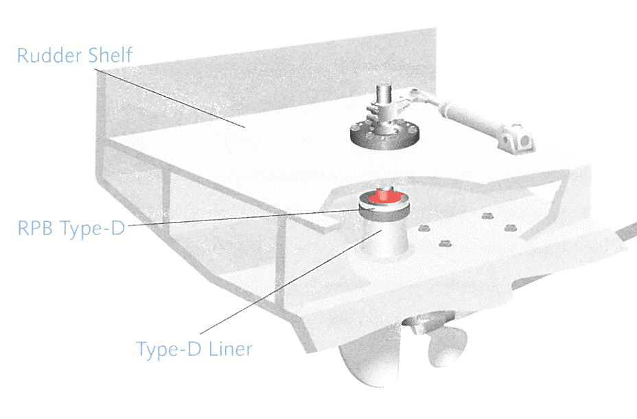
Complete Type-D Installation Guide may be downloaded HERE